1
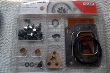
Cummins/Holset Turbo Rebuild kit for H1C and H1D. Part Number 4027309
You will find few extra parts in the kit that are not required on the H1C turbo but are used on the H1D
Disassembly is straight forward, follow the rebuild manual. You may have to use heat, heat/wax, PB Blaster to liberate the Center Housing Rotating Assembly from the Turbine Housing. It can be rusted together very badly.
| 
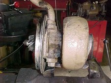
2
The next 3 pictures are the turbo after removal from the engine. Follow the instructions given in the Holset manual packaged with the rebuild kit for disassembly. Be sure to index mark parts as described in the parts rebuild manual. In most cases the CHRA ( Center Housing Rotating Assembly will be heavily rusted to the turbine housing. I had the entire turbo soaking in my parts cleaner for 2 weeks, it did nothing. Serious heat finally broke the rusted joint.
| 
3
|
4
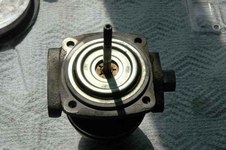
Compressor housing removed
| 
5
All parts are now cleaned for inspection and then painted
| 
6
Look for cracked, bent or damaged blades. Replace with new if any damage is found. Do not attempt to straighten blades.
|

7
Look for cracked, bent or damaged blades. Replace with new if any damage is found. Do not attempt to straighten blades. Inspect bearing journals for scratches and wear. New/Good Journals measure 0.432"
| 
8
| 
9
Inspect turbine housing for profile damage caused by possible contact with the rotor. Chase all threaded holes. Look for any cracks or distortion.
|

10
Inspect Compressor housing profile for damage due to possible contact with rotor. Check that the retaining ring groove is free of deposits. Replace with new if any damage is visable
| 
11
Inspect bearing housing for wear or score marks on both the bearing and piston ring areas. Chase all tapped holes
| 
12
Check diffuser seal bore and replace if scored or damaged. Chase tapped holes
|

13
Diffuser rear side
| 
14
You must install these miniature Circlips deep in the bearing housing. My internal
Circlip pliers were way to large for these clips. I found that needle nose medical tweezers worked quite well
| 
15
Its now reassembly. Please NOT to spill all the little parts ! From now on everything must be clean. No dirt, grunge allowed. The Turbo has the potential to spin up to 140,000 RPM's. Due to the high rotational RPM, normal bearings are not used. This turbo uses oil bearings. They look like bronze bushings, they are not. The shaft turning inside the oil bearing is actually riding on a film of high pressure oil.
|

16
In the top of the bearing housing, you will see two groves for the Circlips. The Circlips have one edge BEVELLED. The bevelled edge MUST face the oil bearing.
Install the lower Cerclip. Then insert one oil bearing, then install the upper Circlip. Then turn the bearing housing over and repeat the process for the lower oil bearing.
| 
17
The next 2 pictures show the oil bearings
| 
18
|

19
Oil Bearings are installed and locked into position with the Circlips
| 
20
Set the heat shield on the bearing housing
| 
21
Install the piston ring seal to the turbine wheel shaft. Gently use your finger nails to expand the piston ring and then slid it down the shaft until it drops in the groove
|

22
From the heat shield side, insert the turbine shaft. ALIGN THE PISTON RING SEAL SO THE GAP IS 180 DEGREES FROM THE OIL DRAIN HOLE !!! SLowly twisting the shaft and pushing in on the piston ring will allow it to move into position. Lubricate the shaft with clean engine oil. Then place the thrust collar on the shaft. Align the balance mark on the thrust collar with that on the shaft.
| 
23
You now need a T-20 Torx socket and a Torque Wrench that reads in Inch Pounds.
| 
24
Lubricate the Thrust Bearing with clean engine oil. Install the Thrust Bearing and then install the 3 flat head screws and torque to 40 inch pounds
|

25
Install a new piston ring on the Oil Slinger
| 
26
Lubricate the Oil Slinger and install in the Diffuser
| 
27
Install the Oil Baffle into the Bearing Housing
|
28
Oil Baffle Installed
| 
29
Use some engine oil on the groove on the opposite side of the diffuser to hold the rectangular ring in position. Take care not to trap the rectangular seal. MARK !! the balance marks on the Oil Slinger with that on the end of the shaft.
| 
30
Align all balance marks; Oil Slinger, shaft and compressor wheel. EMPHASIS !! ALIGN all balance marks.
|

31
Assure that the Balance marks are aligned on the shaft and compressor wheel. Install compressor wheel and locknut NO LOCKWASHER USED. I used a drop of Blue Locktite.
| 
32
Tighten Nut.......THREAD IS LEFT HAND !! and Torque to 150 inch pounds
| 
33
Install the Center Housing Rotating Assembly (CHRA) to the Diffuser using the diffuser screws supplied and torque to 75 inch pounds.
|

34
CHRA and Diffuser ready for install into Turbine Housing
| 
35
Locate the CHRA into the Turbine Housing. BE SURE SCRIBE MARKS ARE ALIGNED !
Using new bolts supplied and clamp plates tighten and torque to 180 inch pounds
| 
36
OK, you forgot to make your scribe marks. The scribe marks are so the High Pressure oil line and the oil return line will be in the proper position when the turbo is mounted. Loosen the bolts in picture 36 so the CHRA will rotate in the turbine housing. Mount the turbo temporarily on the exhaust manifold (only 2 bolts needed). Then rotate the CHRA until the turbo oil return line is in alignment with the Turbo Oil return line on the engine block. Now re tighten the 4 bolts and torque to 180 inch pounds. Now remove turbo from exhaust manifold.
|

37
Install the Turbo oil return pipe aligned as shown in the picture, use the new gasket supplied, torque bolts to 18 foot pounds
| 
38
Install O Ring Seal and then install compressor cover. USE CARE not to damage the Compressor Wheel Blades!!. Align Scribe marks for proper alignment of compressor to Turbo Cross Over Tube to Manifold.
| 
39
Install V Band Clamp and tighten Nut to 75 inch pounds
|
40
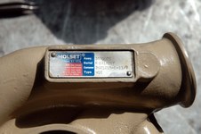
Turbocharger Data Plate
| 
41
Installed on Engine. Prior to attaching the High Pressure oil line, inject 2 cc's of engine oil into the High Pressure fitting on the Turbo. Then Attach high Pressure oil line. Buy a new Turbo Oil Return Hose. Cummins Part Number 3286499. This is special hose to handle the high temperature oil discharged from the Turbo back to the Crankcase. You have just saved yourself about $850.00 by rebuilding your Turbo rather than buying a rebuilt from 'The Chrome C'. It took me roughly 3 hours to totally strip, clean and inspect all parts and then paint. Actually assembly took 2 hrs 15 minutes. Finally, with your fingers rotate the compressor wheel to be sure it runs smooth and does not hit the compressor housing. If it feels good, give her a few good spins.
| |
