 | 1.
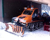
Bombardier Tracked SW-67 (1995 -2025 and ongoing)During the winter of 1995, I tore my Bombardier SW-37 down to the bare belly pan. A total rebuild was done with all wearable parts replaced. The Engine is a Chrysler 265 Industrial 6 cyl, totally rebuilt to zero time. The Hydraulic system was upgraded to 15 gpm at 2500 psi for future needs.
Steel was added on the rear to mount a Braden HU-10, 10,000 pound Hydraulic Winch. A 3 Point mount was built to mount a AmeriEquip 80A Backhoe. The same 3 point mount accepts my Valby chipper that will handle up to 3 inch logs. Fast forward to
Nov 2025. When winter plow season is done, I will look for a hydraulic snow blower to replace the blade. It will be a summer 2026 project to adapt a
blower. I am tired of pushing snow with the blade, on heavy snow winters I start to run out of room to push the snow. |
| 1808 Visits
17 Items
Shared Album | |
|
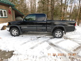
 | | 2.
ENOK (on going) | 563 Visits
2 Items
Shared Album | |
|
 |
| |
| 4.
CUSTOM TRUCK PAINT (May 8, 2023)| Power Point of large truck show in Germany. Crank up the audio ! Click on Power Point Album, let it load. It then self runs |
| 1 Albums
Shared Folder | |
|
 | | 5.
PW Pictures (ongoing) | 5924 Visits
11 Items
Shared Album | |
|
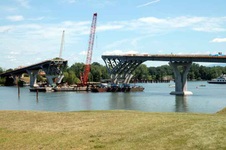 | 6.
crown point bridge (08/03/11)Good Link on Bridge History
http://en.wikipedia.org/wiki/Champlain_Bridge_(United_States) |
| 5064 Visits
23 Items
Shared Album | |
|
 | 7.
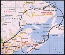
Trans Labrador 2005 (1943 Dodge Carryall Expedition)Until the Mid 1990’s, travel across Labrador Canada was limited to Air, Snowmobile, Dog Sled or Walking. With the Advent of the Trans Labrador Highway or Rt 500 and as the Locals call it, “The Freedom Road” (as it gave them the freedom to move) , one can now drive from Goose Bay/Happy Valley Labrador to Labrador City, Labrador, and then connect to Quebec RT 389, also a wilderness road, ending up at the St Lawrence River.
Since the Trans Labrador Highway was built, I have wanted to drive its length, Connect to Quebec Rt 389 and make a giant circle ending back at home. The actual distance was 3411 miles with 539 miles on various conditions of Gravel Road. In Quebec from Mount Wright to Fire Lake, you drive thru the Iron Ore Mines on old ungraded, washboard, potholes made from mine tailings. This section of the road was worse than terrible. Yet it’s the only access for Labrador City and Goose Bay/Happy Valley (during the winter) by car or tractor trailer.
From Goose Bay to Churchill Falls is a distance of 288 KM with nothing but you and the Gravel…No services of any kind, not even people. And from Churchill Falls to Labrador City it’s a run of 238 Km again with nothing but you and the Gravel. Once entering Quebec on Rt 389, more gravel wilderness road down to the Manic 5 Dam with only one fuel stop at Relais Gabriel. Then continuing on to Baie-Comeau is another 221 KM of desolate beautiful wild country on a rough rolling, narrow, washboard, potholed, Tar road..
In making this wilderness run, you will be driving on 539 miles of Gravel Road. This road has many faces. You will experience loose stone, like driving on Large Marbles, Serious Washboard and Many Miles of driving on Boulder Heads, Narrow Bridges, Steep Grades (18% at Manic 5), Soft Shoulders and Serious Drop Off’s. You will not find Radar Traps. There are no cell phones up there, If you want communication, a Satellite Phone is required. You must be prepared to handle your own problems. Broken Windshields and Flat Tires are a special Hazard.
Serious planning went into this trip. The Carryall, now named “Sweetheart” for how she ran and performed flawless. Only a sticky door lock required some graphite lube in Newfoundland. She ran 3411 miles and consumed 131.64 gallons of Cetane Boosted Diesel for a mileage of 25.9115 MPG. She never skipped a beat, drew large crowds of people, asking all kinds of questions and shooting lots of pictures. I told ‘Sweetheart’ before we left, “You fail me and I will paint you Pink and send you to the Crusher in Mexico” With that our Labrador Adventure Expedition started on July 6, 2005
Labrador now has a new Highway, RT 510 that runs from L’Anse-au-Clair to Cartwright, Labrador. And presently a link is being built that will connect Cartwright to Goose Bay/Happy Valley, Labrador. When this is complete in a few years, it will be possible to drive from L’Anse-au-Clair to Labrador City all on wilderness gravel road. This is one of the last true long distance gravel roads in North America. When you reach North West River, Labrador you are at the END of all roads in this part of North America. To drive further north, one must go to Alberta, Canada. |
| 17424 Visits
417 Items
Shared Album | |
|
 | 8.
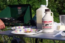
PW Maple Round the World (2003 ongoing)Pictures of PW Maple Syrup Round the World that our Friends have sent. Any picture of PW Maple received will be stored here.
Double click on any picture for full screen size |
| 14779 Visits
81 Items
Shared Album | |
|
 | 9.
Cat Genset (May 20 2009 ongoing)| Install of a 2005 Cat, 20KW Diesel Genset at Moosecreek. Genset has 60.3 hours of exercise time. She had never seen a grid failure when I bought it. |
| 1001 Visits
32 Items
Shared Album | |
|
 |
|
 | 11.
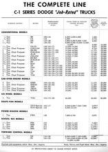
Dodge Power Giant W300 Dodge Power Giant, 1 ton, W300 were built between 1958, 59 and 60 with a total production of only
834.
My W300 will get a Cummins B3.9 engine. Transmission will be a NV-4500 driving into a NP-205 T Case. Hydroboost Disk Brakes and Power Steering are a must have. Smokey will be painted solid Red with Black Line-X Running boards
I have loafed and loitered all summer, now its time to get busy. Tomorrow is a good time to start tearing it apart. Remove the nose and then remove the Gas Guzzling, Spark Infested, 251 Engine, Transmission and T Case LOL ! Then measure and mark up for the Cummins/NV-4500 and NP-205, then remove the cab and strip the frame for blasting. My goal this winter is to build a complete running/driving chassis. Then next spring start on the body work/prep for paint, then final assembly. |
| 24083 Visits
159 Items
Shared Album | |
|
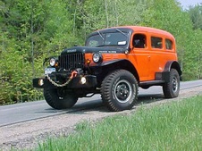
 | 12.
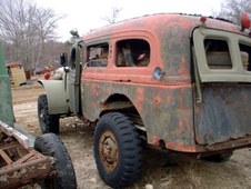
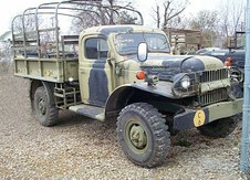
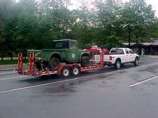
1943 Dodge Carryall (2002/2004)Before buying my Bumblebee, I found a 1943 Dodge Carryall. The Carryall was in terrible condition, more suited for the crusher that a restoration. The Carryall had been in 2000 to the Power Wagon Rally in Fairfield, Iowa to be offered for sale. It was not sold and it returned to Mass and sat looking for a new owner. I still do not know how it made the trip to Iowa and back as it was so structurally weak, It could hardly carry its own weight. I decided I would purchase the Carryall and do a restoration. It was also going to be a learning experience as I had never tackled a job so large on a truck. The Carryall was delivered and sat in my shop while I finished my Bumblebee. When I was ready to actually start work on the Carryall, I got 'cold feet' and decided that the body work required was way over my head. I started looking for a good carryall body. I could not find one and drew a line in the sand, that if one was not found by Thanksgiving 2002, I would start and do my best. It could always be taken to the dump if all went wrong.
From the front A Post on both sides to the tail gate welds, rust had eaten away everything inclding all floor cross members. Doors were shot, roof shot, many stress cracks in the body. The body was racked 6 inches to the left. You could take 2 fingers and rack the body back and forth, seriously 2 fingers. After over a week of trying to figure where to start, I came to a plan, a plan that was followed to completion.
I took 1.000" x 1.000" x 3/16" angle and x braced the body bringing it back to true. Then I cut the sides, inner and outter out of the carryall with my plasma torch. The body panels were fab'ed from 1 piece, 16 gauge sheet. Patterns were made and steel sheet cut. It took 21 days for one outter side to be completed, totally by hand fabrication. Once knowing what had to be done the other side was done in 5 days. One piece, 18 gauge sheet steel was used for the inner skin. Slowly It looked like it really was going to roll again someday. All new fender wells were fab'ed, new cross members from 2.000" x 2.000" x 3/16 tube were fab'ed. Carryalls used a 2 piece tail gate, top lifted and bottom dropped down. My lower gate was so bad there was little hope of repair. I decided that I would use Panel Doors from a 1947 Dodge Panel. The width was correct but they were much to high. These had to be cut down to fit the opening. The new floor in the Carryall was fab'ed from 3/16" steel. A custom rear stem bumper was fab'ed. The seats are 1999 Ford Explorer front and back. Heavy use of Q Pads and Carpet has really made this a quiet running truck. All parts were blasted with Black Beauty and Pickle X applied. Then I shot PPG MP-170 Epoxy Primer, then PPG MP-182 primer on everything. The chassis was shot with PPG MOA Chassis Black, everything else shot with PPG Base/Clear. The Color is Harley Davidson Orange and Black mixed to a reflectance of 37% to give it the always wet look.
From the start of work, I had stuck a Cummins "C" on the front left cowl. This truck was going to get a Cummins 4BTA Engine and the Cummins "C" was my incentative goal. I found a 1999 Cummins 4BTA Recon engine with only 23K miles. Also located a 1999 Dodge NV-4500 (5 speed od) transmission and a 1993 Dodge Married NP-205 T case. The ring and pinions were changed to 4.89's, Saginaw Power Steering was added along with 4 wheel disk brakes. I decided to add a Braden MU-2 Winch which is drive shaft driven. My plan was to power this winch with hydraulic power using the Power Steering pump as Mile Marker Winches do.
The Hydraulic Winch is Bi-directional. The Tires are STA Superlugs 900x16 mounted on Budd Wheels.
My goal was not to build a show truck, I am not a coach builder or body man, but rather a nice driver that I can have fun with. From the begining of the work, I set a Completion date, that it must be done in time for the Power Wagon Rally in Fairfield, Iowa June 2004. Completion was May 14, 2004. |
| 50746 Visits
175 Items
Shared Album | |
|
 | 13.
Bumblebee Power Wagon (2001/2002)Early Preparation work has begun on the Bumblebee to be ready for the Cummins swap as soon as the M37 Bandit is complete this fall. Pictures of the Cummins Conversion will be added at the end of this album.
My Dodge Power Wagon is a 1970 Export Model which served in the Danish Military. When taken out of service, it was returned to the US. I purchased it, during 2001. The restoration started immediatelly. The entire PW was stripped to the bare frame and blasted with Black Beauty. All parts were shot with PPG MP-170 Epoxy Primer, then PPG MP-182 Primer. The Frame was shot with hardned PPG MOA Chassis Black. The rest of the truck was shot with PPG Base/Clear. The PW was stock PW except for the 24 volt electrcal system which was converted to 12 volt and the Military Bed. I located a stock Power Wagon Bed in New Jersey. It was in poor shape and required major work. While rebuilding the bed, I added a 3/16" steel floor and had the entire bed shot with Line-X.
I installed a fresh Chrysler 318 and a NP-435 Transmission. The Divorced NP-200 T case was then reinstalled.
The Ring and Pinion gears were changed to 4.89's. To handle these performance up grades, 4 wheel power disk brakes were added as well as Saginaw Power Steering. The Original Braden MU-2 winch which is Drive Shaft driven required a new Chelsea series 352 bi-directional PTO.
The Tires are STA Superlugs 900x16. To provide clearence in the engine compartment, Helitool Suspended pedals were added replacing the original floor mounted pedals thus allowing the brake Master Cylinder to be moved from the frame location to the fire wall. Custom running boards fab'ed from 3/16" diamond plate were installed.
At the end of the album is the Cummins Diesel o |
| 15407 Visits
88 Items
Shared Album | |
|
 | 14.
M-37 ' Bandit ' Everything will be stripped, all parts blasted with Black Beauty and then primed with PPG MP-170 Epoxy. The frame and under body parts will then be shot with PPG MOA Hardened Chassis Black. Body and interior will be shot with PPG Base/Clear.
The Bandit is powered with a Cummins Recon 4BTA driving into a New Venture NV-4500, 5 speed OD Transmission married to a NP-205 T case. Rear differential is centered and ring and pinions are 4.89's. ARB Air Lockers front and rear.
AGR Performance Saginaw Power Steering, Hydroboost assisted disk brakes on all 4 wheels, Braden LU-4 series hydraulic winch (front) and a 10K pound Superwinch Husky 10 (rear), STA Super Lug 900x16 tires and much more. All parts/components are being rebuilt to Zero Time. |
| 47508 Visits
196 Items
Shared Album | |
|
 | 15.
Hydroboost Brakes for Carryall and PW (Hydroboost on my Carryall)When I built my Carryall, I used a Hydroboost Brake system, supplied by Hydratech. At that time, they were truly a market driven company, supplying a quality product at a reasonable price. Its sad to say, but I no longer feel that applies. In fact, its impossible to even talk with the company any longer, you must go thru dealers. In building my M37, I found that the dealers were not able to answer my questions, and the prices were out of sight.
I set out to find the components to assemble my own hydroboost system, using traditional truck parts, off shelf, and available at any NAPA and GM/Chevy Dealer.
I was able to cut the price almost in 1/4 and still have exactly the same product.
The following hydroboost will work with Power Wagon FFPW's, WC and M37.
All parts are used on 1991 Chevy V3500 trucks;
Master Cylinder 1 & 5/16" bore NAPA 39435 $47.88
Hydroboost Unit NAPA 52-7307 $178.00
You will need to buy the push rod, 2 springs and a baffle from a GM/Chevy Dealer
Push Rod 377397
Spring P155581525
Spring 471736
Baffle 360859
Total Cost for the GM/Chevy parts $49.00
Complete cost for a Hydroboost system using the above parts $274.88
You can have custom made hydraulic hoses made at NAPA
You will need to cut the hydroboost push rod shorter and cut new 3/8" threads. Fabricate
a mount for the hydroboost to fire wall. You can now screw the hydroboost push rod into Helitool Suspended Pedals
Bleeding the air can be tricky. FIll your power Steering pump reservoir almost to overflowing. With the front wheels jacked up off the ground, and engine not running, crank the steering wheel lock to lock a few times. Refill the Power Steering pump reservoir again to almost overflow. Then Start the engine and IMMEDIATELY shut her off. I mean IMMEDIATELY, as soon as the engine starts shut her down. Refill the power steering pump to almost overflow. Repeat, start engine, immediately shut her down. Refill reservoir. Continue doing this until the level in the reservoir does not go down.
Then start the engine and run the wheels to one side lock, shut down the engine and refill the reservoir.....this time to its normal level. Start the engine and rotate the steering wheel to the other side lock. Refill reservoir to its normal level. Then start the engine and run the wheels back and forth lock to lock, shut down and check the level, refill if needed to its normal level. Keep doing this until the level does not go down. Thats it, you have the air out of the system. After sitting overnight, check her one more time as microscopic air will come out of the system and the level may go down a little.
Enjoy your Hydroboost Brakes. |
| 13175 Visits
12 Items
Shared Album | |
|
 | 16.
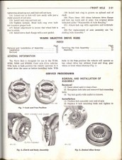
Knuckle Rebuild (February 16, 2005)Does your Power Wagon, M-37 or WC have a lot of play in the steering, shimmy of the tires, wandering on the road, require constant herding of the steering wheel, hard rough uneven effort to turn wheels? Some of the possible causes may lay in front axle Steering Knuckles and or Tie Rod Ends.
Regardless of the condition of your Power Wagon, M-37 or WC, we are dealing with unknown wear on internal parts, unknown prior maintenance and possible parts breakage. It is imperative that during a restoration, rebuild, or a vehicle with the above mentioned problems, that the Front Steering Knuckles be torn down and rebuilt. When I rebuilt my 1943 Dodge WC-53 Carryall, I found the Knuckles in serious condition. I doubt they had been opened since 1943. My M-37 did not indicate any of the above problems, yet on tear down I found serious wear of the top trunnion bronze bushing in the knuckle and seriously worn bearings and cups on the lower trunnion. Without a tear down, these would have never been found. One more important step is replacing the bronze axle bushing and oil seal. Its an easy job with the Knuckle torn down. Everything is in the open.
I am also making a modification to the top bronze bushing. I am changing the bronze bushing to a Timken 23100 bearing and a Timken 23256 Cup. This eliminates the bronze bushings, which are mostly very low quality reproductions, some not even in spec. This modification should also make for smoother steering, at least in theory. The modification is painfully simple, and will be shown in detail as I proceed with rebuilding the Knuckle.
Anyone who can turn a wrench and hold a screwdriver can rebuild a knuckle, its NOT Black Magic. Normal shop tools will do the job. The only one special tool needed is a Split Bearing Puller to pull the lower bearing off the trunnion. You can borrow one or rent it for a few dollars. Or better buy one from NAPA for $33.00 and you have a new tool. I bought the needed parts from Vermont Commercial Salvage in Colchester, VT. They have fair pricing and George is great to work with. The Phone number is 802-864-4762. The following parts are needed to rebuild the knuckle with the added bearing modification. (4) Timken 23100 bearings, (4) Timken 23256 Cups, (2) Gasket and Steel Shim Sets, (2) Sets Felt Rear Knuckle Seals, Gasket and Spring Expander that goes behind the felt, and 5lbs High Temp Wheel Bearing Grease.
Changing the Tie Rod Ends is simple and should be done at this time, as the tie rod must be dropped from each knuckle. When you change the tie rod ends, I will show you how to get the Toe In back to where it was with the old Tie Rod Ends, however when finished you should get on an Alignment Rack to set toe In properly.
You MUST have/use a Dodge Shop Manual to properly do this work. This album shows step by step how to do the job in pictures and text; however much important information contained in the Shop Manual is not re-copied here. Consider this as a supplement to the Dodge Shop Manual
Take your time, do it right, These Knuckles hold the wheels on and control the steering……. IT’S YOUR LIFE!!! |
| 3248 Visits
40 Items
Shared Album | |
|
 | 17.
352 PTO (April 19, 2008)| Double click on first picture for full screen. The you can step thru all the instruction pages in full screen. You can also 'right click' and download the instructions |
| 8005 Visits
11 Items
Shared Album | |
|
 | 18.
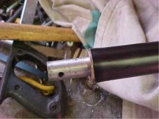
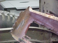
Rivet Removal (May 22 2008)I used this method every time and can remove a backing plate in less than 15 minutes. Also works great on any Frame Rivets
1. Take a 4.5" angle grinder with a 1/16" kerf cutoff wheel. With the angle grinder and cutoff wheel come in from the outside of the backing plate parallel with the backing plate and cut the head off the rivet as close as possible.
2. With the angle grinder and a flap type abrasive grinding disk, grind the end of each of the 5 rivets smooth where you just cut the head off.
3. You will now see the outline of the .500" rivet that has to be removed. Get dead center on each rivet and make a nice deep center punch.
4. Now with a drill your going to drill into the rivet body towards the rear of the rivet. Start with a 1/8" drill bit. Drill the first hole .500" deep. The with a 1/4" drill bit open the hole to 1/4", then with a 5/16" drill bit open the hole to 5/16" and finally with a 3/8" drill bit open the hole to 3/8". Each time you enlarge the hole, be sure to drill all the way to the bottom of the first pilot 1/8" hole.
5. You will now have a hole, 3/8" diameter x 1/2" deep. Use a pair of Large Vise Grips to hold the 3/8" punch so you eliminate the chance of hitting your fingers. Take a 3/8" FLAT nose punch and insert the end in the hole. Now with SAFETY GOGGLES, GLOVES and HEARING PROTECTION, take a hand sledge and Drive the punch. The first blow will have a ring, the second and third blows will have a muffled thud as the rivet moves out. I find it takes about 4 blows and the rivet is out. The backing plate will fall off.
The reason for drilling the holes, ending with 3/8" x .500" deep is this. If you try to drive on the flush rivet body, each blow will cause the rivet to expand just a little in the already tight hole. The more you have to drive on it, the more you expand the rivet and make it even tighter.
By drilling .500" deep hole, 3/8" deep you are driving on the inside of the rivet deep enough that any expansion will not expand the rivet and bind it in the hole.
Although the above procedure details rivet removal on Brake Backing Plates, it also work equally as well on Frame Rivets. |
| 6980 Visits
12 Items
Shared Album | |
|
 | 19.
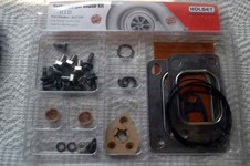
H1C Turbo Rebuild (April 2, 2008)The Holset/Cummins H1C Turbocharger is found on 4BT and 4BTA Cummins Engines. Regardless of the running condition of your Cummins 4B Series Engine, you should check the Axial and Radial play on your Turbo. If you go out of spec limits, your compressor wheel can contact the compressor housing. Serious, Expensive damage is done requiring many new parts.
On Inspection, I found that the H1C Turbocharger for the Bumblebee was close to the maximum specification limits both in Radial and Axial play.
Axial ( Thrust)
Min .0015"
Max .0037"
Radial
Min .0013"
Max .0020"
Rather than buy a rebuilt Turbocharger from 'The Chrome C' for almost $850.00 or buy a used Turbo that might also have wear, I decided to rebuild my own Turbo.
The H1D Rebuild Kit serves both the H1D and the H1C Turbochargers. You will find there are some extra parts and gasket supplied that is not used in the H1C rebuild
This pictorial guide to rebuilding your H1C Holset Turbo DOES NOT replace the manual supplied with the rebuild kit. Nor does it replace the Cummins Shop Manual. But rather is a supplement to both of those documents.
The key is take your time. Read the rebuild manual and look at these pictures. When your sure you understand all procedures then proceed. If your in a grumpy mood or a hurry.......wait for another day !
It is not difficult. If you can read and follow directions you can do it.
The only special tools needed are;
Torque Wrench reading in Inch Pounds
Torque Wrench reading in Foot Pounds
Miniature Internal Circlip pliers or Needle Nose Medical Type Tweezers
Torx T-20 Driver that will fit your Inch Pound Torque Wrench
If you have any questions, click EMAIL at the bottom of the album and I will receive your question and will promptly answer it. |
| 24930 Visits
41 Items
Shared Album | |
|
 | 20.
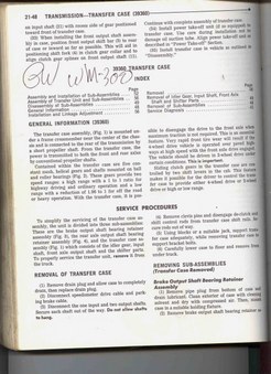
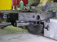
PW Levers NV4500 This modification deals with mounting the Power Wagon Transfer Case and Ebrake Levers on a NV-4500. It also addresses the now blocked transmission lubrication fill hole.
Many people, as I have done, have opted to use the original NP-200 Transfercase and either drive from the traditional right output or drive off the Ebrake drum to a centered rear axle housing. When using the NV-4500 on a Cummins 4B series, length is a critical issue to allow room for the intermediate propeller shaft. The Dodge Versions of the NV-4500, 2 wheel drive transmission have a rear tail cone that is way to long to use without moving the NP-200 to the rear. This would also increase the rear drive shaft angle. In my opinion, the only NV-4500 that allows keeping the NP-200 in the OEM position is the 2 wheel drive, GM Version NV-4500 with the short Tail Shaft. This will allow room for the intermediate propeller shaft and not moving the NP-200.
In 2000, when I re-powered the Power Wagon with a 318 with a NP-435 Transmission, Ray at Helitool sold adapter plates to allow mounting the Transfercase shift levers and Ebrake on the NP-435 using two drilled and tapped bosses and a tab to a PTO port bolt. This worked excellent and in fact it will work with your NV-4500 since it too has 2 drilled and tapped .375" x 16 unused mount bosses.
To utilize this Helitool Adapter plate, all that is required is drilling one hole .375" and cutting off about .500" of the adapter that sticks up past the top of edge of the NV-4500. Instead of using the PTO port bolt for the lower stay, I fab'ed a piece of .250" x 1.5" stock that goes from the adapter plate to the right lower transmission mount bolt. Its that easy to modify this plate for a NV-4500.
However, New Venture did not engineer the GM, NV-4500 or any NV-4500 for that matter for this arrangement. The problem is that the Transmission oil fill port is directly behind our now placed Transfer Case Shift Levers and Ebrake. One would have to remove the entire lever assembly to check or add transmission oil. There is another simple fix!
The Transmission oil fill is tapped .750" Pipe Thread. Remove the .750" pipe plug. Go to NAPA and buy a Weatherhead .750", 90 degree hydraulic street elbow. The part number is 3400x12. You can NOT use a standard plumbing street elbow as its to long. The hydraulic elbow is square and sits close the male pipe threads. You will also need a .750" x 9.0 inch piece of pipe, threaded one end only. For test fitting, dont use pipe thread sealer yet. Screw the street elbow into the oil fill port on the NV-4500 and tighten so that the angle is close to what you see in the pictures. Then try to screw in the 9.0" piece of pipe. You will probably find that the casting ridge on the NV-4500 Case just above the oil fill port sticks out about .030" to far. Take a angle grinder and 'love' off about .030" and you will now be able to screw the 9.0" piece of pipe.
To be sure your angle is correct now mount the Helitool Plate with levers attached to the 2 drilled and tapped bosses on the NV-4500 standing it off the case using 1.0" spacers. You MUST use spacers. If you have the new fill pipe at the correct angle, mark it. Then remove and install thread sealer. I use Permatex Anaerobic Sealer # 51813, I also use Permatex Anaerobic Prep on the threads # 765-1154. Now with sealer on the threads, screw in the Street Elbow and align to your reference marks, then screw in and tighten the .750" x 9" piece of pipe. Now using 1.0" spacers, mount the Helitool Adapter plate to the NV-4500. Use a temporary spacer at the bottom to hold it parallel to the NV-4500. Now fabricate your lower stay from .250" x 1.5" stock, bend a tab and drill a .500" hole for the transmission mount bolt. Fit this in place and cut to the proper length and weld the free end to the Helitool Adapter Plate. Buy a .750" rubber expansion plug for end of your new fill pipe. Adjust the Ebrake and T case shift rods per the Dodge Manual and your good to go.
Since your using a GM Version of the NV-4500, this also mandates using the GM/Cummins Flywheel Housing Adapter. This adapter has a 7.5 degree tilt built into it. Its your choice if you mount the engine off at 7.5 degrees and have the NV-4500 level or mount the Engine level and have the NV-4500 tilted 7.5 degrees. I decided to have the transmission at 7.5 degrees. I will over fill the NV-4500 by 1 quart to keep the lube level on the high side correct. Your new fill tube can also be used to check level. Make a dip stick and mark it for the level you desire. From then on, you can dip the transmission to check level. I leave it up to each person on how to access the filler. You can remove the transmission cover, make a door or other type of opening in the transmission cover, your choice. Using the 1.0" spacers will center the levers in the slots on the transmission cover as seen in the pictures.
If you even think you may be doing a NV-4500 Swap in your PW, M37 or WC and using the original levers, I highly suggest you contact Ray at Helitool; www.uglytruckling.com and inquire about buying the adapter mount plate to mount the levers on a NP-435 transmission. The pictures below show the entire process. |
| 6608 Visits
6 Items
Shared Album | |
|
 | 21.
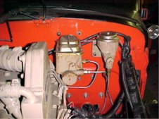
Pressure Cap (Radiator Cap Modification)My WC-53 Carryall is using a Power Wagon radiator. I decided I wanted to run a 12-14 psi pressure system with the Cummins. I had the radiator re-cored, the inlet and outlet were changed to the same size as the in/out on the Cummins. Now I was faced with the problem of how to hide a standard radiator pressure cap. I had two available options; run the fill neck out the top of the radiator shell and just have a pressure cap exposed, or make the original Cap in the radiator shell a dummy and have the real fill under the hood. I did not like either of the options and came up with a way to have the radiator fill come through the radiator shell and still look Stock.
It's a very simple modification. The entire modification can easily be done in the evening after dinner.
1. When you have the radiator shop change the fill neck to a pressure style, you must stress that it has to be exactly the same length as the original fill neck. You want the stick out of the neck exactly the same as stock.
2. Have your radiator shop supply you with a 12-14 psi Radiator Pressure Cap
3. Picture #1. The original Radiator Cap is a 3 piece assembly (not counting the gasket) There is a the outter shell and an inner shell with the locking ears and a round disk under the rolled down area. Notice in the center is a hole surrounded by a rolled down area. You must grind off the rolled down area and the two halfs of the Radiator Cap will separate. You may have to carefully pry some if they are rusted. You can throw away the disk and the inner shell with the locking ears. Cut off and grind smooth the center stud you just removed the rolled end from. The only piece you want is the outter original shell.
4. Now clean up the outter shell to remove all rust and paint to match your radiator shell.
5. You will now need a small amount of Epoxy and Hardner. Use a high quality solvent to remove all grease and oil from the inside of the Original Radiator Cap Shell and the outside of the new Pressure Cap.
6. Picture #2. Put a generous coating of Epoxy on the top of the Pressure Cap and about 1/8" deep on the inside of the Original Shell. Put the top of the Pressure Cap into the original shell and press it down, center it well and fill all round the pressure cap with epoxy. Bring it up almost to the edge of the lip on the pressure cap. Make sure the pressure cap is centered and everything is level. Now let cure for 24 hours.
7. Picture #3. You now have a Pressure Cap, inside the original Shell. Its there forever, The cap on my Carryall has been in place for over 2 years and a little over 5000 miles, you can see in Picture #2 (taken today 12/30/05) it looks like new. |
| 7674 Visits
3 Items
Shared Album | |
|
 | 22.
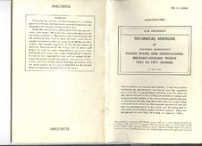
Powertrain Interchanges (TM-9-1808-C)| These pages cover the interchanges of powertrains. Info can be found here on using centered 3rd members. |
| 6371 Visits
9 Items
Shared Album | |
|
 | 23.
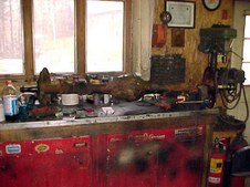
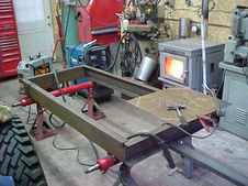
Test Fixture (October 30 2006)I built my Engine Test Fixture using 6 inch heavy channel. The axles are from a mobile home which I shortened to fit the Test Fixture Frame. To shorten the axles, i cut the required length from the axles. These axles are hollow tubes.
I found some hollow tube with the same thickness wall that would slide into the axle tube. I made these short stubs
8 inches long so each stub would fit into an axle side 4.0". Each axle half was marked 3.0" from the open end and then 4 equal spaced .500" holes drilled through the axle ( not the stub). Finally the short stubs were driven into the axles to the pre measured marks. I plug welded the .500" holes to the stub and also ran continuos bead around the entire joint where the axles butted together.
The frame rail width was fab'ed to the same dimension as a Power Wagon frame rail. All joints were prep'ed for full penetration welds, gusset plates were added to the top and bottom of each corner. The tongue is 3.0 x 5.0" heavy channel with the added gussets you see in the pictures. The trailer hitch size is for a 2.0" ball.
No suspension was used. The axle spring perches were welded directly to the 6 inch channel. If this was to be towed on the road, I would have added gussets to the axle/frame junction.
The radiator was found at an auto wrecker. I have no idea what it was used in. I wanted a radiator with hose connections that would match the Cummins hose connections, both in location and size. The electric fan is a 16" that I found on sale at Auto Zone. Its not high quality, but for this application it is fine and the price was right. The electric fan is connected through the Cummins Fan Sensor Switch so engine temperature will control the Fan.
The Fuel tank is just a Plastic 5 gallon fuel container with the top drilled for the feed and return fuel lines
I have a mechanical oil pressure and temperature gauge, volt meter and tachometer installed on the front diamond plate instrument panel. A standard ignition key switch operates the starter and fuel valve. There is a over ride switch for the electric fan. I also have a panel light that comes on when the fan sensor switch signals for the fan to run. Also included is a switch to disable the fuel valve so I can crank the engine without it starting.
In the pictures you can see that the front two Cummins engine mounts are used. The rear mount is the transmission, in this case a SM-465. Later during the winter of 2006/2007, I am going to change the rear mounting to be universal for any transmission or mount without a transmission. My fixture is set up for Cummins 4B Series engines, however you could just as easily mount any Gas Engine by changing the mounting system. Its a totally self contained Test Fixture, with no time limit on operation other than re-fueling a required.
I use a trailer dolly to move the Test Fixture. Even with a full dressed Cummins/Transmission its easy to move with the dolly. |
| 4781 Visits
11 Items
Shared Album | |
|
 | 24.
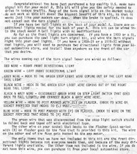
Turn Signal Wiring Diagrams (Turn Signal Wiring)This information covers the Signal Stat series 900 Turn Signals
Double click on any picture for full screen size |
| 53864 Visits
4 Items
Shared Album | |
|
 | 25.
Warn Hubs (From Dodge Shop Manual)This is the service on Warn Hubs as given in the 1967 Dodge PW Shop Manual.
Double click on thumbnail for full screen |
| 3903 Visits
2 Items
Shared Album | |
|
 | 26.
Horn Mods for PW/WC with Power Steering (Horn Commutator)Saginaw Power Steering Horn Modification
When you add Saginaw Power Steering to a Power Wagon or WC or M-37, you loose the ability to use the stock horn button on the steering wheel. Power Wagons and WC's have a hole that goes threw the steering box. This allows the horn button wire to exit the column and not get twisted as the steering wheel is turned. The Saginaw Power Steering Box does not have a threw hole for the horn wire. As such without some type of modifications you will not be able to use the standard horn button as the wire will get wrapped up in both directions as the steering wheel is turned.
I made a commutator for my Power Wagon and Carryall and M37 to eliminate this problem. Many people have asked me for information on how I did this so that they could also regain use of their horn button. The one on the Power Wagon is enclosed in a boot and I did not feel like tearing it all open for pictures. Today I made one for my Carryall and took pictures of the modification.
I selected materials that everyone should have access to. Here is a step by step description of the conversion. It is assumed that you already have the Universal joint mounted on the Saginaw Power Steering Box. |
| 10698 Visits
13 Items
Shared Album | |
|
 | 27.
Power Wagon Dashboard (PW Dashboard remove/install)This is the procedure to remove a Power Wagon Dashboard and replace with a new one. Also included is the procedure to remove the windshield valance and replace, but there are no pictures for the valance.
I have changed dash boards and also the overhead valance where the windshield wipers are located. You will have to do some cutting and welding, its a little tricky but not impossible by any means.
First, if you look under the dash board at each door post, you will see the dash actually extends into the door post. Also while looking at the dash/door post area, you will see 6 or 8 spot welds running vertically between the dash and door post area.
First, you must strip everything out of the old dash board, everything. BY stripping the old dash, you will have the needed room to rotate it upwards as described below. Then you will have to remove the windshield. Look along the bottom of the windshield and you will see a row of spot welds going from side to side of the windshield. These all have to be cut. Using a spot weld cutter makes it quite easy. Then you need to go under the dash and also cut the 6 or 8 spot welds on each side of the dash at the door post. Then take a die grinder with a cut off wheel.
Look at the front of the dash, right at the door post and you will see 2 short welds on each side. These are cut with the cut off wheel.
Now since you removed everything under the dash, ROTATE the bottom of the dash forward toward the firewall and upwards. You will end up with the dash in a horizontal position with the front faceing the floor.
Now with a little wiggling the dash can be cocked a little and it will come right out.
Repeat in the reverse to install the new dash.
To remove the windshield wiper valance on top. Once again with the windshield out, cut the spot welds along the top edge of the windshiled, there are a frew spot welds near the top in the cab and a few short weld beads in the cab near the top. Now the entire windshileld valance will drop out.
This is not a short job, but can be easily done if you go slow and take your time. If the dash does not want to move after cutting the welds mentioned above, you have missed
a spot weld between the inside of the dash and the door post.
Double click on any picture for full screen size |
| 7964 Visits
3 Items
Shared Album | |
|
 | 28.
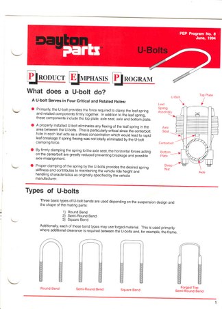
Axle U Bolts (March 4, 2005)I bought new U Bolts for the M-37 today. The U Bolts are made by Dayton Parts Inc. I got a very descriptive document with the U Bolts. Dayton Parts Inc has a web site at www.daytonparts.com
Lots of good technical info also in the Presentation Section of their web site. Double click on the pictures for full screen blow ups |
| 8359 Visits
9 Items
Shared Album | |
|
 | | 29.
NP200 (NP-200 Manual) | 6827 Visits
10 Items
Shared Album | |
|
 | 30.
PW Receiver Hitch (Receiver Hitch PW)Power Wagon Receiver Hitch
RECEIVER HITCH
DRAWTITE/UHAUL # 75098
Bar Code on Hitch 42512 75098
Made for 2000 Jeep Grand Cherokee
Contact me for full details on install
During my PW restoration, I wanted to add a Gooseneck and a Class III Receiver
Hitch. The Gooseneck with removable ball was solved by using a Draw Tite Gooseneck
Platform for the removable ball and doing a custom fabrication on the frame mounts.
The Receiver hitch was not so easy. I tried contacting Draw Tite, Reese and a few other companies that make receiver hitches regarding one that would fit a Flat Fender Power Wagon. I gave them the frame spacing but was told, " we only can look up by application" (we know that is not true) but I was at a dead end. It was either find a
commercial made receiver or fab my own. My time is running short so I wanted the commercial receiver. I went to a Uhaul store (Uhaul handles Draw Tite Hitches). The
owner was helpful, but could not give me a hitch by frame spacing and needed drop.
However he let me go into his hitch stock room and measure all the hitches. After measureing a lot of hitches and counting all the little numbers on the ruller :-), I found Hitch # 75098 the Bar Code Number is 42512-75098.
Most, if not all receiver hitches mount on the bottom of the frame, held in place with
3 to 4 bolts on each side. These bolts and a smile are all that hold your hitch on.
I wanted more !! I wanted the hitch mounts to come up verticle to the top of the frame and then bend over to be bolted/welded. In so doing, all the weight on the receiver hitch is DOWN on the frame, not hanging on some bolts.
Draw Tite / Uhaul hitch # 75098 will do just that. It is NOT an exact drop in, but little work is needed to make it fit perfectly. First the hitch verticle mount plates are
.750" wider than the inside of the frame rail spacing. Second the rear angle brackets from the frame rails to the rear cross member are in the way.
Use my measurements as a guide. The Uhaul man said he sees a wide variation in hitches within a part number. He said the holes are always right, but after that one never knows.
To install this hitch, I had my bed off so things went quicker than with a bed in place. The length of the top flange on the receiver mount is 12.0 inches. I measured back 12.0 inches on each frame rail from the inside of the rear cross member and marked that location. I then measured in .375" from the outside of the frame flange, on each side and scribed a line back 12.0 inches. I then took my Plasma Torch and cut out that area on the top and bottom flange of the frame on each side. The frame is now ready. The square horizontal tube on the receiver hitch sticks out past the mount plates almost .625" on each side. This stick out will cause interference sliding down between the frame rails. I cut that back to .250 and welded. Originally it is only welded on the inside, so this is an easy cut.
With this all done, the complete hitch is dropped in from the TOP, so the mount flanges sit on top of the frame rail and the receiver tube extends just below the rear cross member. The rear of the receiver tube, when everything is in place, will extend
.500" beyond the back of the rear cross member. It is sitting at 21.5 inches off the ground (center of draw bar tube ).
Then with clamps to hold everything in alignment, I Mig welded the top mount flange to the top frame rail. Mig Welded the rear of the verticle mount to the rear cross member. Mig welded the rear of the draw bar tube to the bottom of the rear cross member. Mig Welded the front of the draw bar tube to the bottom of the rear cross member. A small piece of .250 stock was welded back into the area cut out for the mount clearence. With everything welded in place, no strength is lost by cutting that small area from the frame rail flange.
Finally, I put back the rear cornor braces between the verticle mount and the rear cross member and Mig Welded. Everything was acid etched, primed and painted with PPG Frame Black.
DISCLAMIER:
A word of Caution !!!! When you modify a commercial hitch, you void any warantee. You also accept responsibility for the safe installation. You accept responsibility for high quality welds. In no way am I suggesting that this is a Proper Way to mount this hitch, nor am I saying this has been tested as commercial hitches are tested. I have given this as a informational document of how I put a receiver hitch on my PW. However, I suggest that anyone wishing to mount a receiver hitch in this manner, contact Draw Tite, describe the procedure and get their approval in writing. With that out of the way, I can sleep. :-)
As a side note, the Gooseneck hitch is NOT complete in the pictures. Much more steel bracing was welded in prior to completion.
Double click on any picture for full screen size |
| 10369 Visits
5 Items
Shared Album | |
|
 | 31.
Body Builders Layout Dodge Power Wagon Body Builders Layout
WC-53 and WC-57 Drawings Supplied by Ugg
Double click on a picture to enlarge. You can right click to download drawings |
| 12969 Visits
6 Items
Shared Album | |
|
 | 32.
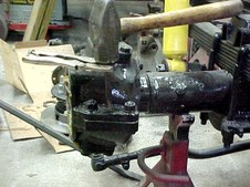
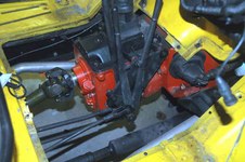
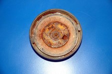
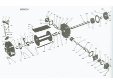
LU4 Winch (Braden LU-4 Winch Rebuild)The LU-4 Series Braden Winch is used on the Dodge M-37 Trucks. The Winch on the 'M-37' suffered a seized winch clutch. The Handle could not be moved. Unlike the Braden MU-2 Series used on the Power Wagons where the winch clutch is exposed, on the LU-4 series it’s enclosed in the right housing. To determine what was seized, exploratory surgery would be required. Since the right housing would have to be totally removed, I decided to totally tear down the winch and replace any worn parts. Without question all seals and gaskets would be replaced. Other parts would be replaced on a 'as need' basis.
The pictures of the disassembly are in order and as I found it.
Someone had not assembled the winch correctly. See if you can spot the mistake. If you get to
picture 18, you have missed the error. As a result of the assembly error, someone had to make a modification to complete assembly.
The Braden Series LU-4 and the Series MU-2 share the same design concept in the worm drive unit and bronze worm gear and main winch drum shaft. The cable drum and right hand declutching of the winch are different. As you tear down a LU-4, its easy to see that a MU-2 is a much more robust winch.
I was easily able to lift a complete LU-4 with no cable from the floor to the workbench. I can’t do that with a MU-2.
Once everything was opened up, it was easy to see that over the years water had run down the winch clutch shifter shaft and seized it in place. A complete inspection showed the bearing cones and cups on the worm drive to be in excellent condition. All bronze bushings showed no wear, hardly an indication of shafts rotating. Clearly this winch had been used very little if at all, or it was rebuilt.
There is nothing difficult about rebuilding a LU-4; anyone with normal tools should have no problems. I have tried to take photos of each step, along with a description of the process being done. After total strip down, all parts were washed in a parts washer to get rid of the crud and grease that destroys the action of a blast cabinet. Once cleaned up, all parts were blasted with glass beads, with absolute protection given to gasket surfaces, bushings and bearing cups. Then a very careful final cleaning in virgin solvent and everything is ready for paint. All parts are primed with PPG MP-170 Epoxy Primer. Then shot with PPG MOA Hardened Chassis Black. The resulting paint will have a Black Satin finish. Then the final assembly. |
| 33151 Visits
56 Items
Shared Album | |
|
 | 33.
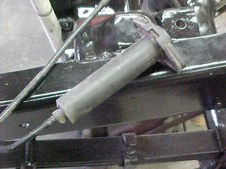
NV-4500 Slave Fitting Modification (NV-4500 Slave Mod)When installing an NV-4500 Transmission (Dodge Version ) in one of our Power Wagons or WC's, the process is quite straight forward. However, when you go to plumb the NV-4500 Clutch Slave Cylinder to a Stock Clutch Master Cylinder on the older Dodges, problems arise. If you bought your slave cylinder from a auto supply parts store, you will find it does not come with the connection fitting. I have check all over and can not find this fitting. Dodge sells the Assembly, Slave Master Cylinder and interconnect hose WET, ready to mount and use. There is no provision to fill the system nor bleed it I will show you how to make a NV-4500 Clutch Slave work with our older Dodge Clutch MC’s, and explain how to fill and bleed the system. What I am showing, is tried and proven on my Cummins Carryall with a NV-4500 in over 9000 miles of use.
Since the special fitting that couples the interconnect hose to the slave is not available, you will need to go to a salvage yard and get the interconnect hose from a wrecked truck. Any truck that uses a Dodge NV-4500 will have the needed interconnect hose. This hose has the special fittings on each end. The hose is made from some type of plastic material that is pushed on the barbed ends of the special fittings. The hose is so tough, Dodge does not use clamps to secure it to the fitting. Follow the description of work under each picture and you will not have any problems. |
| 791 Visits
7 Items
Shared Album | |
| |
